Lithium-Ion Battery Cell Design: From Formulation to Encapsulation
Upload Time:
Jul 01, 2025
Lithium-ion batteries power modern electronics and electric vehicles through a precisely engineered core (cell). Here are nine key design steps:
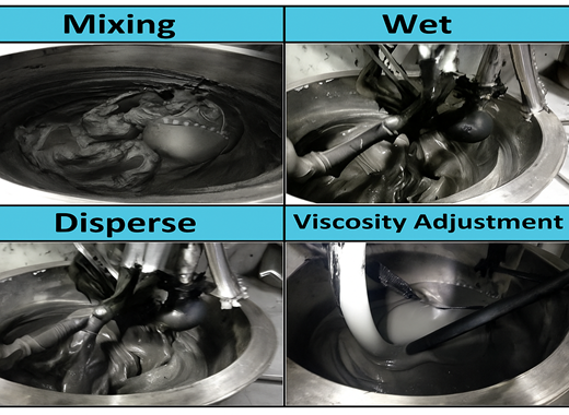
1. & 2. Electrode Formulation: The Foundation
-
Cathode: Cobalt oxide (LiCoO₂), lithium iron phosphate (LiFePO₄), or similar active materials, mixed with conductive additives (e.g., acetylene black), binders (PVDF), and coated onto an aluminum foil current collector.
-
Anode: Primarily graphite, blended with conductive additives (acetylene black), binders (PVDF), and coated onto a copper foil current collector.
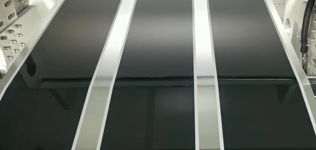
3. Current Collector & Coating Design: Current Pathways
Metal foils carry active material coatings with specific parameters:
| Active Material | Coating Density (g/cm³) | Current Collector Basis Weight (g/m²) | Coating Thickness (μm) | Substrate Material (Density g/cm³) |
|---|---|---|---|---|
| LiCoO₂ | 1.7~2.4 | 1.2~1.7 | 100~150 | Al (2.7~2.8) |
| LiMn₂O₄ | 1.7~2.0 | 1.2~1.7 | 90~110 | Al (2.7~2.8) |
| NCM (LiNiCoMnO₂) | 1.7~2.1 | 1.2~1.7 | 120~160 | Al (2.7~2.8) |
| LiFePO₄ | 1.6~1.8 | 1.1~1.3 | 125~140 | Al (2.7~2.8) |
| Graphite | 0.9~1.1 | 0.6~0.8 | 200~300 | Cu (8.9) |
4. Anode Excess Design: Buffer for Safety
During initial charging, the Solid-Electrolyte Interphase (SEI) layer forms on the anode, permanently consuming lithium ions. Thus, the anode’s design capacity must exceed the cathode’s to ensure sufficient lithium for cycling.
5. Capacity Design: Targets & Assurance
-
Rated Capacity: Required energy output (Operating Current × Operating Time).
-
Design Capacity: Typically 10%~20% higher than rated capacity to ensure reliability and lifespan. Calculated as:
Design Capacity (Ah) = Coating Areal Density × Active Material Ratio × Active Material Specific Capacity (mAh/g) × Coated Electrode Area -
Design Margin: Accounts for manufacturing variations, ensuring batch capacity meets specifications.
6. & 7. Electrolyte: The Ion Highway
-
Type Selection: Tailored to application needs:
High-Temperature, Standard, Low-Cost, High-Voltage, Low-Temperature, High-Rate. -
Electrolyte Components:
-
Lithium Salt (e.g., LiPF₆): Provides lithium ions.
-
Solvent (e.g., EC/DMC blend): Dissolves salt and transports ions.
-
Additives: Enhance performance (e.g., SEI formation, flame retardancy, conductivity).
-
-
Key Parameters: Ionic conductivity, thermal/chemical stability, operating temperature range.
8. Separator: The Critical Barrier
Prevents short circuits while enabling ion flow between electrodes:
-
Materials: Microporous membranes—single-layer PE (polyethylene), double-layer PP/PE (polypropylene/polyethylene), or triple-layer PP/PE/PP.
-
Thickness: Common options: 25μm, 35μm, 40μm (balances safety and ion conductivity).
9. Encapsulation: Aluminum Laminate
Protects pouch cells:
-
Thickness: 88μm, 113μm, 122μm, or 153μm.
-
Structure: Three primary layers bonded by adhesive:
Outer: Nylon (barrier protection)
Middle: Aluminum foil (moisture/oxygen barrier)
Inner: CPP (cast polypropylene; heat-sealable layer).
Conclusion: Designing a lithium-ion cell is a symphony of precision—from electrode formulation and current collector engineering to capacity margins, electrolyte optimization, separator selection, and final encapsulation. Each step critically impacts performance, safety, and longevity. Mastering these principles unlocks the potential for efficient, reliable energy storage.
Design Flow:
Electrode Formulation → Current Collector/Coating Design → Anode Excess → Capacity Design → Electrolyte Selection → Separator Selection → Laminate Encapsulation
Relevant News


